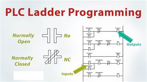
Ladder Diagram Language – The most commonly used graphical programming language for PLC
Ladder Diagram (LAD, LadderLogic Programming Language) is the most commonly used graphical programming language for PLC, and is known as the first programming language for PLC.

Program Introduction
Ladder Diagram (LAD, LadderLogic Programming Language) is the most commonly used graphical programming language for PLC, and is known as the first programming language for PLC.
The ladder diagram language follows the form of relay control circuit. The ladder diagram is derived from the simplified symbols based on the commonly used relay and contactor logic control. It has the characteristics of image, intuitiveness, and practicality. It is easy for electrical technicians to accept it. It is currently the most used PLC programming language.
In the PLC program diagram, the left and right busbars are similar to the power lines controlled by relays and contactors, the output coil is similar to the load, and the input contact is similar to the button. The ladder diagram consists of several levels, arranged from top to bottom. Each level starts from the left busbar, passes through the contacts and coils, and ends at the right busbar.
Format of Ladder Diagram
Ladder diagram is a visual programming language. It uses the connection combination of contacts to represent conditions and the output of coils to represent results to draw sequential control circuit diagrams. The drawing of ladder diagrams must be carried out in a specified format. The relevant regulations are as follows:
(1) Like the execution order of PLC programs, the writing order of the logic lines that make up the ladder diagram network is also written from top to bottom and from left to right. The vertical line on the left side of the ladder diagram is called the starting bus, and the vertical line on the right side is called the ending bus. Each logic line always starts from the starting bus and ends at the ending bus (the ending bus can be omitted).
(2) Each logic line consists of one or more branches. The branch on the left side is composed of contacts, which represents the control conditions; the rightmost end of the logic line must be connected to the output coil to represent the control result. The output coil always ends at the right bus, and the output coil with the same label can only be used once.
(3) In the ladder diagram, each normally open and normally closed contact has its own label to distinguish each other. Normally open and normally closed contacts with the same label can be reused multiple times, with no limit on the number of times.
(4) The contacts in the ladder diagram can be connected in series or in parallel, but the output coils can only be connected in parallel, not in series.
(5) The program end symbol “END” should be used in the last logic line of the ladder diagram to tell the compiler system that the user program ends here.
Basic principles of ladder diagram programming
(1) The contacts in the ladder diagram cannot appear on the right side of the coil.
(2) The contacts should be drawn on the horizontal line, not on the vertical line.
(3) The principle of left-heavy and right-light, top-heavy and bottom-light should be met. That is, when the parallel blocks are connected in series, the branches with more contacts should be placed on the left side of the ladder diagram; when the series blocks are connected in parallel, the parallel branches with more contacts should be placed on the top of the ladder diagram.
(4) It is not advisable to use double coil output. If the coil of the same component is used twice or more in the same ladder diagram, it is called double coil output. When double coil output is used, only the last time is valid, so it is generally not advisable to use double coil output.
Features
Ladder diagram language is the most commonly used language, and it has the following features:
It is a graphic language that uses the terms and some graphic symbols such as relay contacts, coils, and series connections in traditional control diagrams. The left and right vertical lines are called left and right busbars, and the right busbar is often omitted.
The contacts (contacts) in the ladder diagram are only normally open and normally closed. The contacts can be switches of PLC input contacts or contacts of PLC internal relays or the status of internal registers, counters, etc.
The contacts in the ladder diagram can be connected in series or parallel at will, but the coils can only be connected in parallel and not in series.
Internal relays, counters, registers, etc. cannot directly control external loads, and can only be used as intermediate results for internal use by the CPU.
PLC scans events in a cycle and executes in sequence along the ladder diagram. The results in the same scan cycle are left in the output status register, so the value of the output point can be used as a condition in the user program.
In addition, the ladder diagram programming language corresponds to the electrical schematic diagram, which is intuitive and corresponding; it is consistent with the original relay control and is easy for electrical designers to master.
The difference between the ladder diagram programming language and the original relay control is that the current in the ladder diagram is not the actual current, and the internal relay is not a real relay. When applied, it needs to be treated differently from the original relay control concept.

